

As a software developer or product manager, you already know how important use cases are for explaining system behavior to stakeholders. The tricky part is turning that into a diagram that actually makes sense to everyone in the room.
Figuring out who the actors are, when to use include versus extend and how to draw system boundaries correctly takes more than just drawing boxes and arrows. Most examples you find online don’t explain the reasoning behind the structure, which makes them hard to learn from.
In this guide, I’ll share 10 use case diagram examples across banking, retail, restaurants and more. Each one shows a different way to map these elements so you can find a structure that fits your own system.
Bonus: You can create your own use case diagrams using Venngage’s AI Diagram Generator and use case diagram templates. No design experience is required!
What is a use case diagram?
A UML use case diagram is a visual representation of the functional flow of a system, showing how users interact with it to achieve specific goals. It outlines the relationships between actors (users or external systems) and the various use cases (functions or services) the system provides. This type of diagram helps model user-system interactions, making it easier to define the system’s scope and requirements.
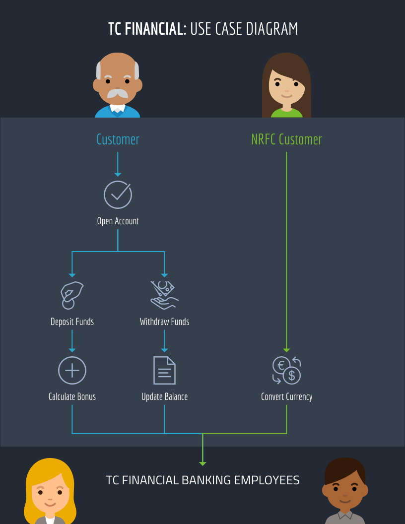
For example, this use case diagram visualizes how customers interact with a banking system, illustrating functions like checking balances, transferring funds, or applying for loans:
In Unified Modeling Language (UML), use case diagrams are used during the early stages of system design to capture the high-level behavior of a system. They help teams understand and communicate what the system should do from a user’s perspective, making them an essential tool in functional analysis and software development.
Simple use case diagram examples
Here are some use case diagram templates and examples to guide your diagram creation process:
1. Simple ATM use case diagram example
Designed for automated teller machine (ATM) systems, this use case diagram portrays different types of transactions as use cases.
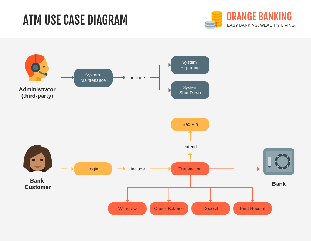
As this example is very simple and contains only essential elements, it can be adapted for other banking systems like branch banking or online banking.
2. Retail use case diagram
This use case diagram example depicts the internal functions and employee interactions within a retail system.
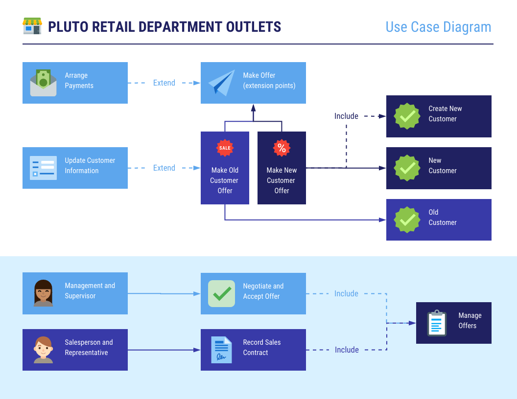
It features basic system functions represented by color-coordinated boxes to signify use cases based on the user’s role. A use case diagram like this can be of great use to retail stores with B2C e-commerce systems.
3. Restaurant use case diagram
In this example, a restaurant’s daily operations serve as the system, the staff represent the actors, and their tasks are the use cases.
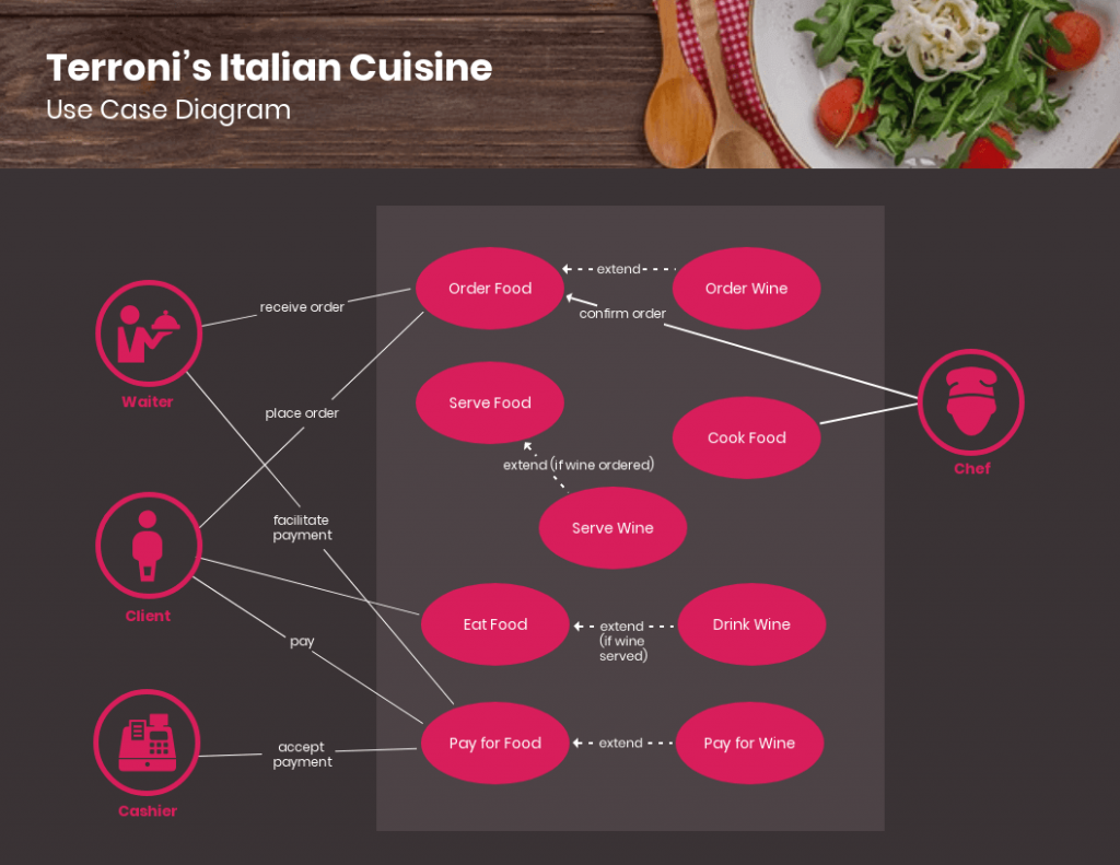
This use case diagram can be particularly helpful to restaurants or fast-food chains in terms of systemizing routine processes and presenting day-to-day activities to employees in a simpler and more orderly way.
4. Travel use case diagram
Here is a use case diagram that maps out how different types of users can engage with a travel booking website or application.
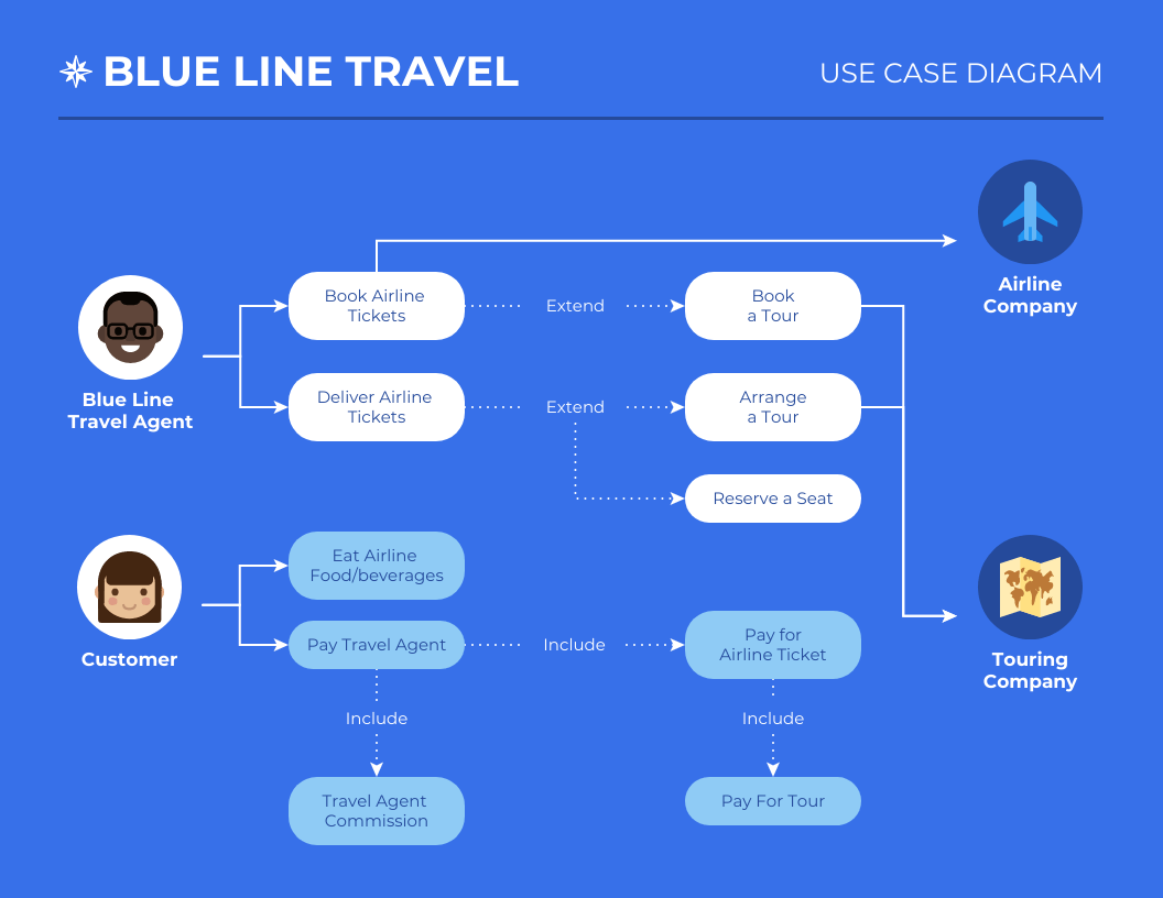
This comprehensive template includes extended use cases marked by dotted lines and arrows instead of simple lines. It can be scaled down or up for hotels, airlines, and other travel reservation systems.
4. Consumer electronics store use case diagram
Last but not least, this use case diagram example illustrates how sales and management teams can use a retail system to carry out tasks.
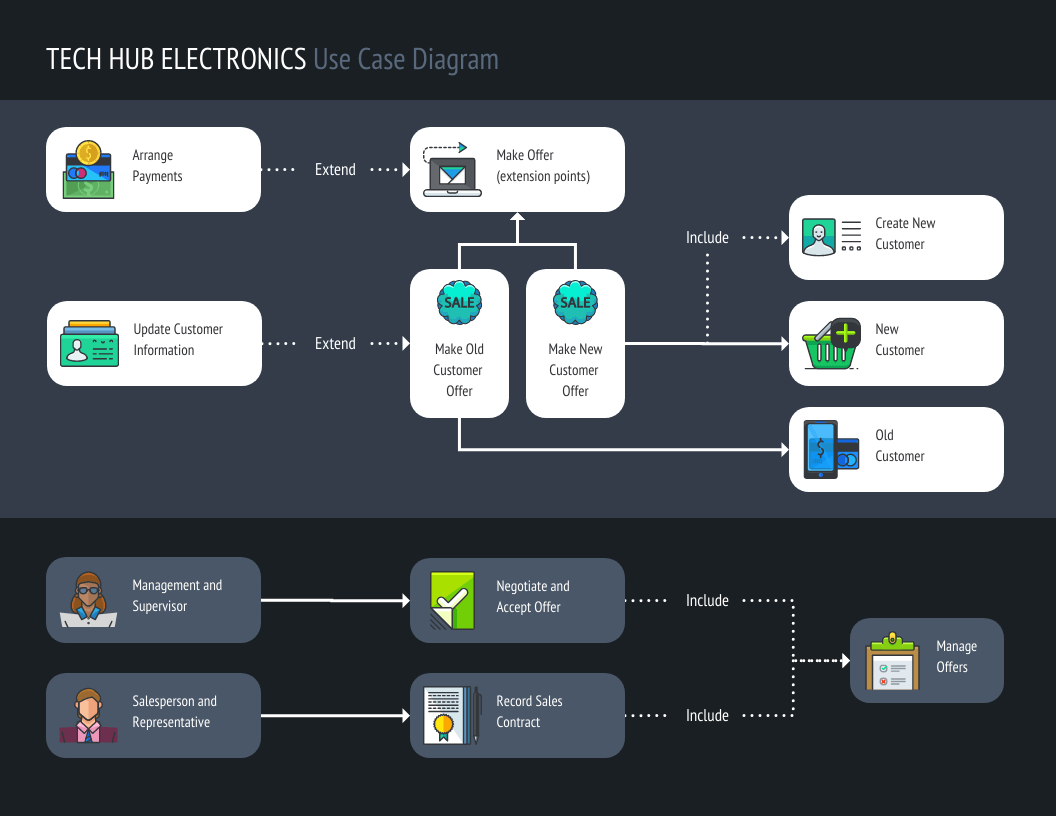
It can be applied to retail systems for consumer electronics and home appliances, fast-moving consumer goods, and other retail sectors.
Financial use case diagram
This simple use case diagram is perfect when you just need to map out the basics without overcomplicating things. It clearly shows how users interact with a system, from logging in to making a request, or getting support, using a clean, easy-to-follow layout. It’s great for planning features, aligning teams, or giving stakeholders a quick overview of how everything connects.

Main components of a UML use case diagram
A use case diagram has four core building blocks. Whether you want your use case diagram to be simple or in-depth, it should include the following basic components:
- Actors: An actor is anyone who performs an action using your system. Actors or users can be a person, an organization, or an external system. For example, in a banking diagram, the customer and the bank employee are both actors. They are represented by stick figures in a use case diagram.
- Use cases: These are the different uses or applications that your system can offer users. If we consider the banking use case diagram example, use case would be ‘check balance,’ ‘transfer funds’ and ‘apply for loan.’ Use cases appear as horizontal ovals inside the system boundary.
- System boundary: The system boundary defines the scope of what your diagram covers. Everything inside the rectangle is part of the system. Everything outside it, including the actors, is external. It is the line between what our system does and who interacts with it.
- Associations: Associations are the lines that connect actors to use cases. They show which actor triggers or participates in which function. A solid line between a customer and ‘check balance’ means the customer initiates that action. More complex relationships like include, extend and generalization use different line styles to show when one use case depends on another or when an action only happens under certain conditions.
Use case diagram relationships in UML
The relationships between elements are where most people get confused. Here is what each one means and when to use it.
Association
An association is a connection between an actor and a use case. It shows that the actor participates in or initiates that action. You can use it any time an actor directly interacts with a use case.
Example: A customer connects to Checkout via an association line, showing they are the one initiating that action. Visually, it appears as a simple solid line between the actor and the use case oval.
Include
An include relationship means one use case always triggers another. The included use case is a required part of the base use case and cannot be skipped. Add it when a use case cannot be completed without another use case running first. It appears as a dashed arrow pointing toward the included use case, labeled with the word include in double angle brackets.
Example: Checkout includes Payment. Every time a customer checks out, payment processing always happens.
Extend
An extend relationship means one use case optionally adds behavior to another, but only under certain conditions. This one is required when a use case sometimes triggers additional behavior. It’s added as a dashed arrow pointing back toward the base use case, labeled with the word extend in double angle brackets.
Example: Apply Discount extends Checkout. A discount is not applied on every order, only when a promo code is entered or a condition is met.
Don’t confuse this with extend. Include means the relationship is mandatory. Extend means it is conditional.
Generalization
Generalization shows that one actor or use case inherits the behavior of another. It works like a parent-child relationship. When two actors share the same use cases but one has additional capabilities, or when two use cases share common behavior with one being a specialized version of the other.
It’s shown as solid line with a hollow arrowhead pointing toward the parent actor or use case.
Example: Admin and Support Agent both inherit from Staff. They share common actions like logging in and viewing tickets, but Admin has additional capabilities that Support Agent does not.
How to draw a use case diagram step-by-step?
Writing a use case diagram involves deconstructing processes in order to reveal a basic overview of your system. Here are some steps that you can follow:
Step 1: Define the system scope.
Decide what your diagram is covering before you draw anything. Is it the entire application or just one module? This stops the diagram from growing too large.
Step 2: Identify the actors
List every person, system or external entity that interacts with your system and categorize them by role. In an e-commerce system, actors might include a Customer, Admin and Payment Gateway. Don’t add actors that only interact with other actors and not with the system itself.
Step 3: Define the user goals and use cases
Pick one actor and list the actions they need to perform. Each action becomes a use case. Focus on what the actor wants to achieve, not the technical steps behind it.
Step 4: Write a short use case scenario first
Write one to two sentences describing what the user does and how the system responds. This helps you spot duplicates or use cases that should be merged before you start drawing.
Step 5: Draw the system boundary
Draw a rectangle and label it with the system name. Place all use cases inside it and leave all actors outside. The boundary makes it immediately clear what is part of your system and what is external to it.
Step 6: Connect actors to use cases
Draw a solid line between each actor and the use cases they participate in. Each line represents an association. Keep it simple at this stage and only connect what is directly relevant.
Step 7: Add include, extend or generalization only where needed
Look for optional behaviors or shared actions. Add relationships only where they genuinely clarify the diagram, not everywhere.
Step 8: Review for clarity and scope
Repeat steps 2 to 7 for each actor type. Then check that the diagram still reflects your original scope and can be understood by someone who wasn’t involved in building it.
If you would rather not start from scratch, Venngage’s AI Diagram Generator helps you design a structured use case diagram with a simple text prompt. You describe the actors, the system and the key interactions and the generator maps them out automatically.
It works well when you know what your system needs to do but aren’t sure how to structure it visually. Instead of placing elements manually, you get a draft diagram to react to and refine.
Why use a use case diagram
Use case diagrams aren’t just for system architects, they’re actually super helpful for anyone trying to make sense of how a system should work. Here’s why they’re worth using:
Common mistakes to avoid in use case diagrams
Even experienced teams make these errors when building use case diagrams for the first time:
- Including too many use cases: Not every system function needs its own use case. If the diagram has more than 10 to 15 use cases, it is likely capturing implementation details instead of user goals.
- Making actors too granular: A Registered Customer and a Guest Customer can often be represented as a single Customer actor with generalization added only if their interactions genuinely differ.
- Overusing extend and include: These relationships add complexity. Only add them when they clarify something that a plain association line cannot show.
- Putting process steps inside use cases: A use case is a goal, not a workflow. “Enter credit card details” is a step. “Complete payment” is a use case.
- Forgetting secondary actors: Systems like payment gateways, email services or third-party APIs are actors too. Leaving them out creates an incomplete picture of how the system actually works.
Use case diagram vs. flowchart
People often get confused between a flowchart and a use case diagram because both involve users and actions. However, they serve different purposes.
- A use case diagram shows what a system does and who interacts with it. It captures scope and relationships at a high level without showing the order in which things happen.
- A flowchart shows how a process works step by step. It maps the sequence of decisions and actions from start to finish.
FAQs about use case diagrams
What is a good use case diagram example for beginners?
A banking or ATM diagram is one of the clearest starting points. The actors are easy to identify (customer and bank), the use cases are familiar (check balance, withdraw cash, transfer funds) and the system boundary is obvious. It gives you a simple structure to follow.
Is a use case diagram the same as a flowchart?
No. A use case diagram shows what a system does and who interacts with it and is used to define scope and requirements. A flowchart shows how a process works step by step. It helps map the logic or sequence of a specific process.
What is included and not included in a use case diagram?
A use case diagram includes actors, use cases, the system boundary and relationships like association, include, extend and generalization. It does not include implementation details, process steps, data flows or the order in which events happen. If you need to show sequence or logic, a flowchart or sequence diagram is a better fit.
Create a use case diagram
The hardest part of a use case diagram is deciding what belongs in the system, which actors matter and when a relationship like include or extend is actually useful.
Once you focus on user goals and keep the diagram high level, the structure becomes much easier to read and build. That means clearer requirements, faster stakeholder alignment and fewer surprises during development.
If you’re ready to map out your own system, start with a Venngage’s Diagram Generator use case diagram template and use the examples above as a reference.