

Last updated on July 2026: Reviewed for UML terminology, diagram notation and Venngage template accuracy
An activity diagram is a UML diagram that shows how a process moves from one action to the next, including decisions, loops, parallel tasks and responsibilities. If UML notation feels confusing, the easiest way to learn it is through examples. This guide walks through a simple login process, an online checkout, a student enrollment workflow and several other scenarios, plus the symbols and steps you need to draw a clear activity diagram of your own.
What is an activity diagram?
An activity diagram is a behavioral diagram within UML, or Unified Modeling Language. UML is a standardized notation for visualizing how software systems are structured and how they behave. An activity diagram maps how a process moves from start to end, including its actions, decision points and parallel tasks. It describes how a process happens rather than how a system is built, which is why teams use it in software design, business process modeling, system analysis and use case documentation.
This notation comes from the Object Management Group’s UML specification, which keeps it consistent across tools and industries.

How activity diagrams fit into UML
Diagrams under UML fall into two groups: structural diagrams, which describe how a system is organized, and behavioral diagrams, which describe how a system acts over time.
Activity diagrams belong to the behavioral group. They model what happens when a process runs from start to finish, including the order of actions, the conditions that change that order and any tasks that happen at the same time.
While most activities run in sequence, an activity diagram can also show two or more actions happening at the same time, such as generating an order number while sending a confirmation email.
What are activity diagrams used for?
Activity diagrams support different stages of a project. During planning, they map out a workflow before any code or process is built. During requirements gathering, they show how a use case actually unfolds step by step. During design, they help describe the logic behind a method, function or operation.
Beyond software projects, teams also use activity diagrams to:
- Model a business process from start to finish
- Illustrate how a system behaves over time
- Document the rules or logic that govern a process
- Clarify a use case before development begins
- Simplify a workflow that involves several teams or decision points

Simple Activity Diagram Example: User Login
Before working through more advanced scenarios, it helps to see a basic activity diagram in action. Here is a simple example based on a user logging into an application.
The process follows these steps:
- Start
- User enters a username and password
- The system validates the credentials
- Decision: are the credentials valid?
- Yes: the system shows the dashboard, and the process ends
- No: the system shows an error message and the user retries the login
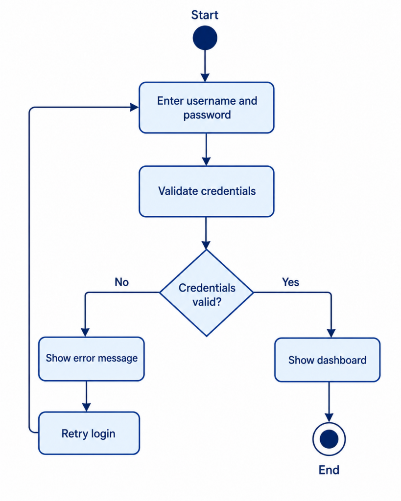
This simple example already uses the core building blocks of an activity diagram. Rounded rectangles represent actions, such as entering credentials or validating them. The diamond represents a decision node, where the flow splits based on a condition. Arrows show the control flow connecting each step, and the start and final markers define the boundaries of the process.
Key elements and symbols in an activity diagram
Activity diagrams are often compared to flowcharts because both show how a process moves from one step to the next. What sets an activity diagram apart is the specific set of symbols it uses to represent actions, decisions, parallel tasks and responsibilities. The table below covers the elements you will see most often.
| Element | Symbol | What It Means | When to Use It |
|---|---|---|---|
| Initial node | Starting point | Use once at the beginning of the process | |
| Action/activity | A task or step | Use for actions like “Validate payment” | |
| Control flow | Direction of movement | Use to connect actions | |
| Decision node | Branch based on a condition | Use for yes/no or conditional paths | |
| Merge node | Combines alternative paths | Use after branches rejoin | |
| Fork node | Splits into parallel tasks | Use when tasks happen at the same time | |
| Join node | Synchronizes parallel tasks | Use when parallel tasks must finish before continuing | |
| Object node | Data or object used or created | Use for documents, orders, forms or records | |
| Object flow | Movement of data or object | Use when showing data passed between actions | |
| Swimlane | Groups actions by role | Use when responsibilities matter | |
| Final node | End of the process | Use when the workflow is complete |

Use decision and merge nodes for alternative paths. Use fork and join nodes for parallel paths. A decision asks which path the process should take, while a fork means two or more tasks happen at the same time.

More activity diagram examples
Once the basic symbols feel familiar, it helps to see them applied across a range of common scenarios. Each example below outlines the actors involved, the steps in the flow and what the diagram demonstrates.
Online shopping checkout activity diagram
Scenario: A customer completes a purchase on an ecommerce site, and the system needs to confirm inventory, process payment and send confirmation in parallel.
Whose involved: Customer, system, payment gateway
Flow:
- Customer clicks checkout
- System checks inventory
- Decision: are the items in stock?
- Customer enters shipping and payment details
- System processes payment
- Decision: was payment successful?
- Fork: generate order number and send confirmation email at the same time
- Join
- Display order confirmation
- End
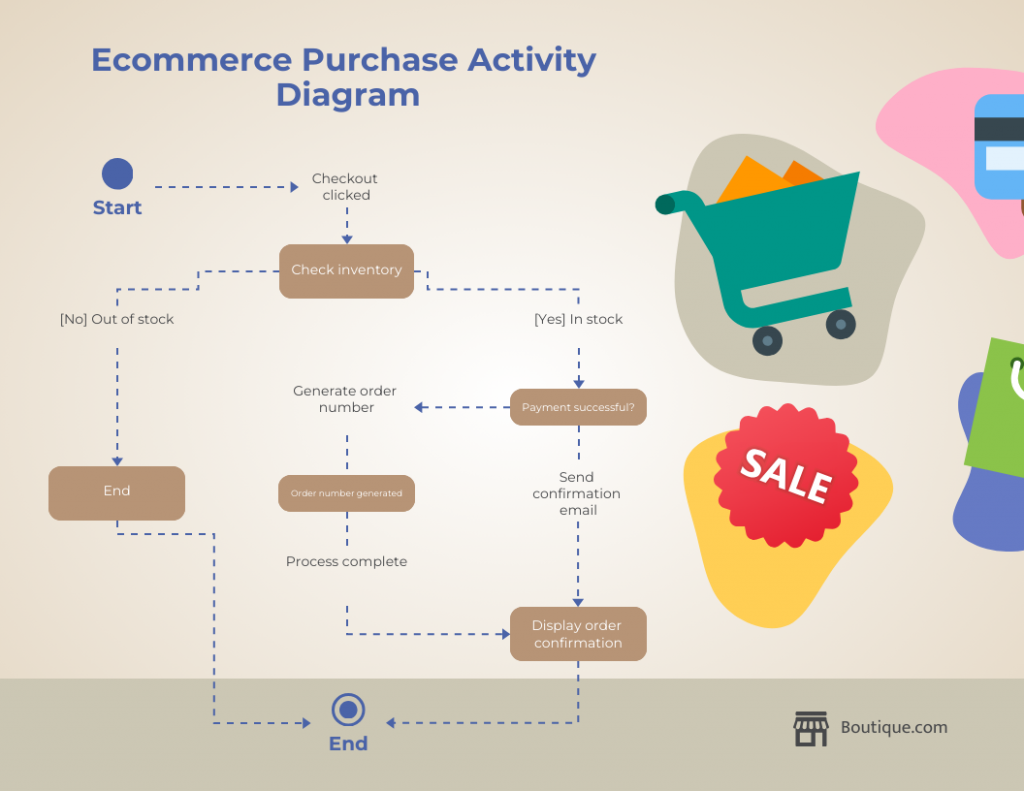
This example demonstrates how fork and join nodes let two independent tasks, generating an order number and sending a confirmation email, run at the same time instead of one after the other.
Student Enrollment Activity Diagram
Scenario: A student registers for classes through a registration system, with the registration division reviewing and confirming the request.
Whose involved: Student, registration system, registration division
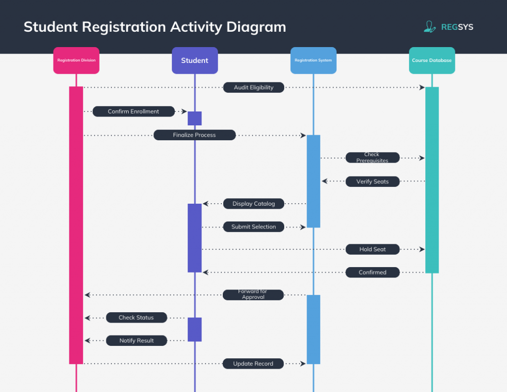
The diagram follows the student selecting courses, the system checking availability and prerequisites, and the registration division confirming or rejecting the enrollment. It shows how a single workflow can span more than one actor without losing clarity, as long as swimlanes separate each actor’s responsibilities.
This example demonstrates how swimlanes keep a multi-actor process easy to follow, since each column shows exactly who is responsible for each step.
Library management activity diagram
Scenario: A library patron searches for a book and either borrows or reserves it depending on availability.
Whose involved: User, library system
Flow:
- User searches for a book
- System checks availability
- Decision: is the book available?
- Borrow or reserve the book
- Update inventory
- Generate due date
- End
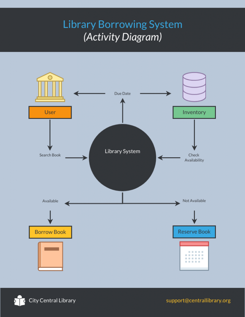
This example demonstrates a straightforward decision node that determines whether the next step is a loan or a reservation, which is a pattern that shows up across many inventory-based systems.
Order processing activity diagram
Scenario: A retailer receives an order and needs to handle billing and fulfillment as separate but coordinated tasks.
Whose involved: Order system, billing department, fulfillment team
Flow:
- Receive order
- Fork into billing and fulfillment
- Decide delivery method
- Ship order
- Join billing and shipping completion
- Close order
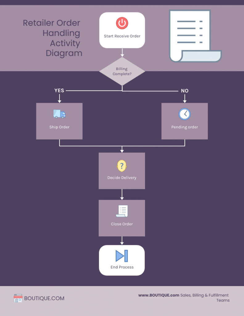
This example demonstrates how a fork can split one process into two parallel branches that later rejoin at a join node, which keeps the diagram accurate when departments work independently before a process can close.
Payment processing activity diagram
Scenario: A customer initiates a transaction and the system validates and authorizes the payment before confirming the result.
Whose involved: Customer, system, payment gateway
Flow:
- Customer initiates transaction
- System validates payment details
- Payment gateway authorizes the payment
- Decision: approved or declined?
- Send confirmation or show a failure message
- End
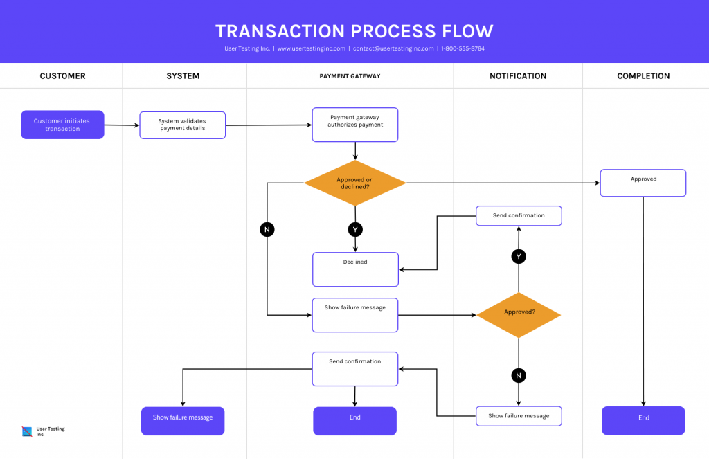
This example demonstrates a clean single decision node with two outcomes, which makes it a useful starting template for any process that ends in approval or rejection.
Try the UML diagram maker to adapt any of these scenarios, or start from an activity diagram template and swap in your own process.
How to draw an activity diagram step by step
Drawing an activity diagram becomes much easier once the process is broken into a few clear stages, from defining scope to refining the finished diagram.
1. Define the process scope and list actions
- Pick one process or use case
- Identify the start and end points
- Avoid modeling an entire system in one diagram
Use verb-led action labels so each step reads as a clear task:
- Validate payment
- Check inventory
- Send confirmation
- Review application
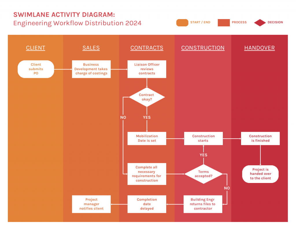
2. Identify actors and swimlane
- Add swimlanes only when responsibilities matter
- Use lanes for user, system, admin, payment gateway, department or external service
3. Organize the flow with decisions, forks and joins
- Use diamonds for decisions
- Label decision arrows with guard conditions, such as [approved], [rejected], [in stock] or [payment failed]
- Use fork and join only for true parallel tasks
- Make sure every branch leads somewhere
4. Create the diagram in Venngage
With the flow mapped out, you can build the finished diagram using Venngage’s UML diagram maker.
- Open Venngage’s UML diagram maker
- Choose an activity diagram template
- Rename the diagram based on the process
- Add or remove swimlanes
- Replace placeholder text with verb-led action labels
- Add decision nodes and label each branch
- Use fork and join nodes for parallel tasks
- Share for comments or export as PNG or PDF
5. Review and refine the diagram
Before sharing the diagram, run through this checklist:
- Does the diagram have one clear start?
- Does every path lead somewhere?
- Are decision paths labeled?
- Are action labels short and clear?
- Are swimlanes assigned correctly?
- Are fork and join nodes used only for parallel work?
When should you use an activity diagram?
Use an activity diagram when you need to:
- Model a business workflow
- Explain a use case
- Show system behavior over time
- Document conditional logic
- Show parallel processes
- Clarify responsibilities between users, systems or departments
- Identify bottlenecks or missing paths
However, an activity diagram is not the right fit for every situation. Use a different diagram when the goal changes:
- Use a class diagram to show object or class structure
- Use a sequence diagram to show message timing between objects
- Use a data flow diagram to show data movement and storage
- Use BPMN for formal business process notation
Activity Diagram vs Flowchart
An activity diagram is similar to a flowchart, but it is part of UML and uses more formal notation for system behavior, parallel tasks, object flows and swimlanes.
Frequently asked questions about activity diagrams
What is an activity diagram with an example?
An activity diagram is a UML diagram that shows the flow of actions, decisions and responsibilities in a process. A simple example is a login flow: a user enters credentials, the system validates them, and a decision node routes the process to either the dashboard or an error message depending on whether the credentials are valid.
What is the starting point of an activity diagram?
The starting point of an activity diagram is the initial node, shown as a solid black circle. Every activity diagram begins with exactly one initial node, which marks where the process starts before the first action takes place.
Can ChatGPT create UML activity diagrams?
ChatGPT cannot render a diagram image directly, but it can generate the underlying code for one, typically in Mermaid or PlantUML syntax. You can paste that code into a compatible diagram tool to render the visual, then move it into a dedicated UML diagram maker for further editing and formatting.
Create your own activity diagram
You do not need to master every UML rule before you can build a useful activity diagram. Start with one process, define where it begins and ends, and add each action in order. Bring in decisions, swimlanes, forks and joins only when they make the workflow easier to follow, not because the notation allows it.
Once the flow is mapped, the diagram becomes more than a technical reference. It turns into a shared point of reference that developers, stakeholders, teams and clients can all read the same way, whether the process is a login screen, a checkout flow, a student enrollment or an internal business workflow.
Use one of the examples above as a starting point, or customize a Venngage UML activity diagram template to build your own.